Lab1
Objectives
This lab is an introduction to programming with Arduino. Since the system on which you are going to be working is specific to the test circuit board, you will therefore develop an embedded system.
In the first part of the lab, you will learn how to:
- Use the Arduino integrated environment or IED;
- Communicate between the computer and the Arduino board;
- Read sensors on digital ports
- Send control signals on digital ports; et
- Write to the LCD Screen.
In the second part of the lab, you must design and implement a state machine using the state machine pattern that you have learned in EEE320.
You have three weeks to complete this laboratory. Tasks 1 to 5 are relatively easy, do not spend too much time on them. Task 6 is difficult and should take the majority of your time for this lab.
Introduction
The microcontroller on the circuit board is programmable uising the Arduino language, which is based on the Wiring language which itself is a subset of C/C++. Programming will therefore be extremely similar to what you have done in EEE243 and EEE435. One of the major difference with the C/C++ programs that you have seen thus far is that you only need two functions in order to have an executable program:
setup(): a function that only executes at the beginning and that can be used to perform the initial configuration.loop()– a function that executes in a loop as long as the board is powered.
For more details on Arduino, take a look at the Arduino introduction.
The laboratory is not a detailed tutorial. We give you references to read so that you can get the implementation details by yourselves.
Task 1: Transmission on the serial port
The first task that is in any early stage of programming is the famous “Hello World!”. We will not stray from this tradition in this lab.
As we have mentioned earlier, there are only two functions required for an Arduino program (setup() et loop()). These are created automatically by the Arduino IDE as you create a new project (called sketch in the IDE).
Now launch the IDE (type “Arduino” in the start menu), there will already be an empty sketch that was created. All you have to do is to add your code and load it on the board. Make sure that the board is connected and that the correct port is selected. To do this, go to (Tools > Board > Arduino Mega or Mega 2560). Once this configuration is performed, you can launch the console (Tools > Serial Monitor). There should be no errors.
Although we have installed an LCD screen on the board, we will not use it to display a message initially. We will use serial port communication instead to send a message to the computer and display it to the console of the IDE.
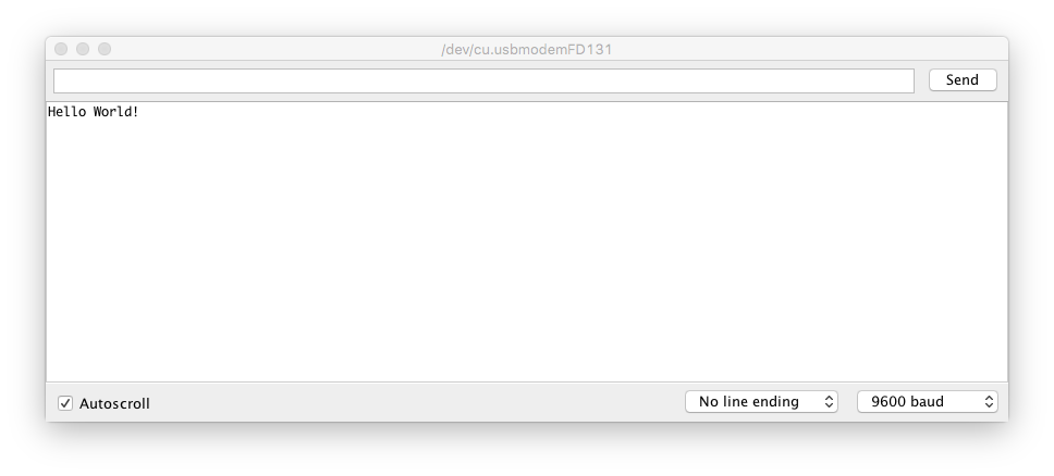
Arduino provides a library to communicate with the serial port. This library is included by default. All you need to do is to initialize the Serial class with the begin() method and to display something with the print() function. After you have read the pages applicable to the Serial class and its methods here), display only once the “Hello World!” message on the serial port.
Insure that you save your project with a name like task1_Lapointe_Beaulieu.ino. To complie, you must click on  or type in combination Ctrl+R (⌘R on Mac). To send your program on the board, click on
  or Ctrl+U (⌘U on Mac).
You should see something like this on your serial monitor. Note that in the lab, there seems to be some garbage characters that sometimes get printed ahead of your message. Just ignore them.
The Arduino library also provides time management functions. The delay() method allows you to pause the execution. You can find more details on the function here. There also exists some functions returning the elapsed time since the start of execution (you will need to do some research here).
You must now display display the time since the start of execution in 1s intervals. Note that the print() method does not function like the printf() in C. You cannot therefore write printf("time: %d\n", time);.
Save, compile and load your program. You should see something like this in your serial monitor:

Perform a demonstration of your program for the instructor before proceeding to the next task.
Task 2: Receiving on the serial port
In the previous task, we transmitted information on the serial port, but we have not accepted any information from the host computer. This is what we are going to do now.
Create a new project and name it something like task2_Lapointe_Beaulieu.ino.
We will again be using the methods of the Serial class ( Reference). You must verify if something is present in the buffer of the serial port (available() method) and read the content interpreting it like a string of character. Note that in C++ there is a class of type String.
You must write a program that asks the user to enter his\her name and then displays the name followed by a greeting, and then asks for another name. You do not want to display anything as long as the user has not pressed the “Enter” key and you do not want to display a supplementary line.
Save, compile and load your program. You should see something like this on the serial monitor:

Demonstrate your program to the instructor before you carry-on with the next task.
Task 3: Writing on a digital port
We will now start to use the board to deal with the real world. In order to do so, we will use the digital ports to turn on light emitting diodes that are located on the test board available from the instructors.
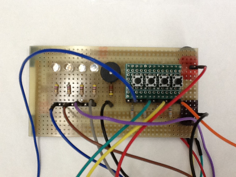
To start, plug in the ground and the power on the GND and VCC ports respectively. Then plug the diodes on the digital ports 22, 24, 26, 28 using wires and connectors available in the lab. Before going any further, show your setup to the instructor.
When your setup is ready, you can create a new project within the IDE (Give it a name similar to the preceeding ones).
In order to use the digital ports, you must first indicate to the microcontroller if it is an input or output port. You can do this with the pinMode() method. You can then write on the port indicating the voltage (LOW or HIGH). The test board uses the inverse logic, which means that a low voltage turns the LED on and high turns it off.
For this task, you must write code that turns on LEDs one after the other, with an interval of 0.5 seconds.
Save, compile and load your program. Give a demonstration to the instructor before going to the next task.
Task 4: Reading of a digital port
Now that you can write on a digital port, you will perform reading an input from a port.
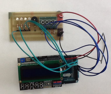
Connect the push buttons on the test board on the digital ports 32, 34, 36, 38.
The final setup should look something like this:
Instead of starting a new project, save the project of task 3 under another name (Ctrl+Shift+S on Windows and Cmd+Shift+S on Mac).
You must now turn the LEDs when the corresponding button is pressed and turn the LED off when the button is released.
Save, compile and load your program. Demonstrate your program to the instructor before moving on to the next task.
Task 5: Display on the LCD screen
The last task before you have to resolve a real problem is that of displaying something on the LCD screen.
The additions on the basic Arduino board are called shields and they come with different configurations. The one we will use for this lab is a shield with LCD screen from DFRobot.
You will have to instal the LiquidCrystal library in order to use the functions that exist for the shield. To install a new library in the Arduino IDE, go into Sketch > Include Library > Manage Libraries and find the LiquidCrystal library. Install the most recent version.
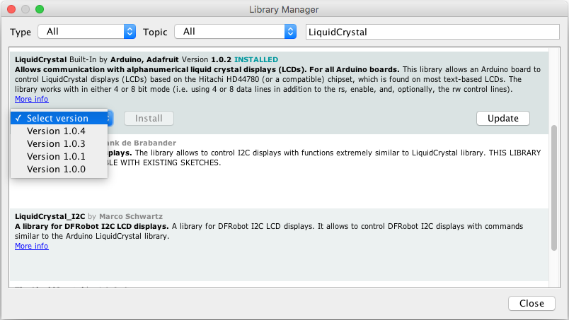
When the library is installed, you only need to include (#include <Library_name.h>). The documentation on how to use the shield can be found here.
All you need to do for this exercise is to ask the user to enter his\her name in the serial monitor (on the LCD screen) and to display “Hello” and the name of the user on the LCD for 6 seconds, then ask for another name.
Save, compile and load your program. Give a demonstration to the instructor before moving to the last part of the lab.
Task 6: A light dimmer
For this final task in the lab, you must develop a light dimmer that behaves as follows: Each light has the same behaviour and uses the button that corresponds to it in order.
- The light is off initially
- The light turns on in full intensity when the push button is pressed
- The light stays on until the corresponding button is pressed again
- If the button remains pressed for more than a second, the intensity of the light reduces to 0 and then rises again to full intensity.
- The button must remained pressed for 3 seconds for the intensity to go all the way to 0
- The reduction in intensity must be continuous (you cannot define a set of discrete levels of intensity)
- When the minimal intensity is reached, there is a 0.5 second delay before the intensity starts to increase again
- If the button is released when the intensity is 0, the next time a button is pressed, the light turns on to full intensity
- If the button is pressed twice in less than 0.5 second, the light starts to flash at max intensity and frequency of 2 Hz The LCD screen must indicate the state in which the system is.
Before you start coding, you must create one or more state machine diagram(s). Use an iterative approach to your design.
In order to simplify the design, we require you to use the state pattern. Here is a partial UML diagram for the design using the state pattern.
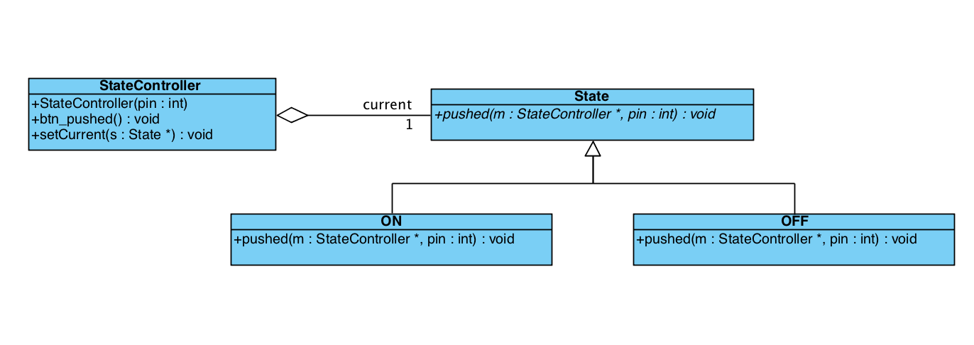
You must include a class diagram and one or more state diagrams. You can use the software you want to create the diagrams, but we suggest LucidChart. Insert your diagrams in your report. Make sure that they are legible.
As you will have noticed, you must do object oriented programming and therefore program in C++.
Download the following file, unzip it and open it in the Arduino IDE. It is an example that uses objects to make a LED flash with the Morse code pour SOS.
In order to implement the state pattern, you must use inheritance and method overloading.
You can create a sub-class by giving your sub-class the following header:
class Sub : public Super {

};
To declare abstract methods in the super-class, you must use the key word virtual in the declaration of the method:
class State {
  public:
    virtual void pushed(int pin, StateController *m);
};
If you want to create a reference to a class from another one, use the following syntax:
class StateController
    {
        class State *current;

      public:
        StateController(int pin);
        void btn_pushed();
      private:
        int _pin;
    };
It is possible to initialize objects like this current = new OFF(pin);
Finally, once you want to apply a method on the object, you must proceed as follows current->pushed(_pin, this);
We recommend that you start with the Morse code example and that you add classes and sub-classes as you progress, compiling often. The first modification that you can do is to activate one of the functions of the Morse class with a button.
You can read more on C++ here.
Provide a demonstration to the instructor.
Lab report
Your lab report should include a cover page, a brief introduction, discussion and conclusion.
Your discussion should explain the design using the UML diagrams and text when necessary. You have to briefly explain what you have learned, findings that you have made, what was challenging in the lab. The discussion must not be a list of steps followed or empty sentences on the usefulness of the lab. Do not regurgitate the lab instructions back. Be concise! One paragraph of good discussion is worth a lot more than 10 pages of fill.
Use the following format for your report.
Submission
You must submit your lab report in PDF format and your code by e-mail in a .zip file.